| **Condition** | **Behaviour** |
|---|---|
| Power ON | Self-test, System OK (green) |
| Fault | Fault LED (yellow), Fault relay NO, buzzer |
| Fire | Fire LED (red), fire alarm out, buzzer |
| Activation | Activation LED blinking (solid after discharge), warning out, buzzer |
 ## Indicators and buttons
**1. Activation buttons**
For manual activation in case of fire hold both buttons for at least 3 seconds to activate the aerosol generators. The aerosol generators will be activated after an activation delay set during commissioning (typically 20 seconds).
**2. Hold / Isolate / Restart Ventilation button**
The hold/isolate input serves more functions:
**Hold** functionality, which temporarily delays the activation of the aerosols after the activation procedure has started.
**Cancel** functionality, pressing the button for at least 20 seconds will cancel the activation.
**Isolate** functionality, which permanently disables the activation of aerosols while work is being carried out in the protected area.
**Restart Ventilation** functionality; During activation, any ventilation systems or similar connected to the FS10 ventilation output will be shut down. After extinction of the fire, the ventilation may be turned on again by pressing the button.
**3. OK indicator**
The OK indicator (green) is lit under normal operation. Note that under all circumstances at least one indicator on the FS10 front panel must be lit. Please consult the FS10 Service Manual for further details.
**4. Fault indicators**
If a fault condition is detected by the FS10 system, the corresponding fault indicator (yellow) will be lit.
**5. Hold indicator**
The hold indicator is lit when hold function is active (i.e., when the Hold button (2) is pressed).
**6. Activate indicator**
The Activate indicator (orange) will be blinking during the activation delay period and will be permanently lit when aerosols have been activated.
**7. Detector reset button**
Button for resetting detectors in alarm state.
**8. Detector indicators**
The relevant detector indicator(s) will be permanently lit if a connected Manual Call Point is in alarm state or blinking if a connected automatic detector is in alarm state.
**9. Mode indicators**
Indicators showing whether the FS10 panel is in automatic or manual mode. In manual mode activation can only happen by pressing the Activation buttons (1) or by using an external activation switch. In automatic mode activation can be started by 1 or 2 active detector inputs or manually as in manual mode.
**10. Mode selector button**
If configured; switch between automatic and manual mode, hold the button for at least 3 seconds.
**11. Mute / reset / lamptest button**
This button works for both faults, alarms, lamptest and fault conditions:
**Faults:**
If a fault is detected, the corresponding indicator is lit, and the internal buzzer and the fault condition is signalled to any external device connected by pressing the button, the internal buzzer is muted.
When the fault condition has been remedied, the fault indicator and the external fault output may also be reset by pressing the button.
**Fire:**
If fire is detected, the corresponding indicator is lit, and the internal buzzer and the fire condition is signalled to any external device connected, by pressing the button, the internal buzzer is muted.
**Lamptest:**
To make a lamptest, press and hold button for \> 3 sec.
**Fault conditons:**
If a fault occurs, press button for \> 3 sec. and LED will show fault pattern, see [7.2](#common-faults) [Common Faults](#common-faults).
**12. Internal buzzer**
The internal buzzer is turned on when a fault condition is detected or when a detector input goes to alarm state. It will also be bleeping when activation of aerosol generators has been started.
## Indicator table
| **Name** | **LED** | **Meaning** |
|---------------|----------------|----------------------------|
| System OK | Green | System operational |
| Faults | Yellow | Fault present |
| Fire Alarm | Red | Fire detected |
| Activation | Orange (blink) | Delay running |
| Activation | Orange (solid) | Aerosol discharge complete |
| Detector Zone | Red | Detector active |
## Interaction Table
| **Action** | **Response** |
|-----------------------------------------|----------------------------|
| Press both activation buttons | Delay begins |
| Press Hold/Cancel | Delay stops / cancel |
| Press Isolate \> 3 sec. | Isolate Aerosol Generators |
| Detector activation | Fire alarm |
| Fault detected | Fault alert |
| Restart ventilation, ONLY after release | Ventilation ON |
# Normal Operation
## Power-On Behaviour
- System OK LED must turn green.
- Fault LED must be off.
- No audible fault indications.
## Monitoring Mode
The FS10 continuously monitoring aerosols, power, switches, and internal circuits.
FS10 also monitoring external detectors, fire alarms and warning devices, if configured so.
## Daily Check (Recommended)
- Verify System OK (green).
- No faults active.
- No fire alarms active.
- External switches in correct positions.
## Manual vs Automatic Mode
### Manual Mode
Activation must be triggered by operator or external activation switch.
### Automatic Mode
Activation may occur when 1 and 2, or 1 or 2 detector zones trigger (depending on configuration).
## Buzzer Patterns
| **Pattern** | **Meaning** |
|----------------|----------------------|
| Constant beeps | Fault |
| Repeated beeps | Activation delay |
| Constant beeps | Activation completed |
## Prohibited Operator Actions
- Do not open enclosure.
- Do not rewire.
- Do not disconnect aerosols.
- Do not change internal configuration.
# Fire Alarm Operation
## Fire Detection
- Fire LED (red).
- Buzzer active.
- Fire relay active.
## Automatic Activation Sequence (if enabled)
- Fire detected.
- Activation delay begins.
- Activation LED blinks.
- Warning devices activate.
- Aerosol discharge occurs after delay.
## Manual Activation Procedure
- Press and hold both activation buttons simultaneously for ≥ 3 seconds.
- Activation delay begins.
- Activation LED blinks.
- Warning devices activate.
- Aerosol discharge occurs after delay.
## Hold/Cancel
- Delay time can be hold if button is pressed.
- Cancel activation by pressing button ≥ 20 seconds.
## Ventilation Shutdown and Restart
- Ventilation OFF during activation.
- Restart ventilation manually when safe.
## After a Fire Event
- Restart ventilation.
- Confirm fire extinguished.
- Technician inspection required.
## Sticker, user quick guide
- The sticker, enclosed to the FS10 Main Unit, gives a quick introduction to the user of the FS10 Main Unit.
- It is recommended to setup the sticker next to the FS10 Main Unit, making all able to use the FS10 Main Unit in an emergency situation.
- Sticker:
## Indicators and buttons
**1. Activation buttons**
For manual activation in case of fire hold both buttons for at least 3 seconds to activate the aerosol generators. The aerosol generators will be activated after an activation delay set during commissioning (typically 20 seconds).
**2. Hold / Isolate / Restart Ventilation button**
The hold/isolate input serves more functions:
**Hold** functionality, which temporarily delays the activation of the aerosols after the activation procedure has started.
**Cancel** functionality, pressing the button for at least 20 seconds will cancel the activation.
**Isolate** functionality, which permanently disables the activation of aerosols while work is being carried out in the protected area.
**Restart Ventilation** functionality; During activation, any ventilation systems or similar connected to the FS10 ventilation output will be shut down. After extinction of the fire, the ventilation may be turned on again by pressing the button.
**3. OK indicator**
The OK indicator (green) is lit under normal operation. Note that under all circumstances at least one indicator on the FS10 front panel must be lit. Please consult the FS10 Service Manual for further details.
**4. Fault indicators**
If a fault condition is detected by the FS10 system, the corresponding fault indicator (yellow) will be lit.
**5. Hold indicator**
The hold indicator is lit when hold function is active (i.e., when the Hold button (2) is pressed).
**6. Activate indicator**
The Activate indicator (orange) will be blinking during the activation delay period and will be permanently lit when aerosols have been activated.
**7. Detector reset button**
Button for resetting detectors in alarm state.
**8. Detector indicators**
The relevant detector indicator(s) will be permanently lit if a connected Manual Call Point is in alarm state or blinking if a connected automatic detector is in alarm state.
**9. Mode indicators**
Indicators showing whether the FS10 panel is in automatic or manual mode. In manual mode activation can only happen by pressing the Activation buttons (1) or by using an external activation switch. In automatic mode activation can be started by 1 or 2 active detector inputs or manually as in manual mode.
**10. Mode selector button**
If configured; switch between automatic and manual mode, hold the button for at least 3 seconds.
**11. Mute / reset / lamptest button**
This button works for both faults, alarms, lamptest and fault conditions:
**Faults:**
If a fault is detected, the corresponding indicator is lit, and the internal buzzer and the fault condition is signalled to any external device connected by pressing the button, the internal buzzer is muted.
When the fault condition has been remedied, the fault indicator and the external fault output may also be reset by pressing the button.
**Fire:**
If fire is detected, the corresponding indicator is lit, and the internal buzzer and the fire condition is signalled to any external device connected, by pressing the button, the internal buzzer is muted.
**Lamptest:**
To make a lamptest, press and hold button for \> 3 sec.
**Fault conditons:**
If a fault occurs, press button for \> 3 sec. and LED will show fault pattern, see [7.2](#common-faults) [Common Faults](#common-faults).
**12. Internal buzzer**
The internal buzzer is turned on when a fault condition is detected or when a detector input goes to alarm state. It will also be bleeping when activation of aerosol generators has been started.
## Indicator table
| **Name** | **LED** | **Meaning** |
|---------------|----------------|----------------------------|
| System OK | Green | System operational |
| Faults | Yellow | Fault present |
| Fire Alarm | Red | Fire detected |
| Activation | Orange (blink) | Delay running |
| Activation | Orange (solid) | Aerosol discharge complete |
| Detector Zone | Red | Detector active |
## Interaction Table
| **Action** | **Response** |
|-----------------------------------------|----------------------------|
| Press both activation buttons | Delay begins |
| Press Hold/Cancel | Delay stops / cancel |
| Press Isolate \> 3 sec. | Isolate Aerosol Generators |
| Detector activation | Fire alarm |
| Fault detected | Fault alert |
| Restart ventilation, ONLY after release | Ventilation ON |
# Normal Operation
## Power-On Behaviour
- System OK LED must turn green.
- Fault LED must be off.
- No audible fault indications.
## Monitoring Mode
The FS10 continuously monitoring aerosols, power, switches, and internal circuits.
FS10 also monitoring external detectors, fire alarms and warning devices, if configured so.
## Daily Check (Recommended)
- Verify System OK (green).
- No faults active.
- No fire alarms active.
- External switches in correct positions.
## Manual vs Automatic Mode
### Manual Mode
Activation must be triggered by operator or external activation switch.
### Automatic Mode
Activation may occur when 1 and 2, or 1 or 2 detector zones trigger (depending on configuration).
## Buzzer Patterns
| **Pattern** | **Meaning** |
|----------------|----------------------|
| Constant beeps | Fault |
| Repeated beeps | Activation delay |
| Constant beeps | Activation completed |
## Prohibited Operator Actions
- Do not open enclosure.
- Do not rewire.
- Do not disconnect aerosols.
- Do not change internal configuration.
# Fire Alarm Operation
## Fire Detection
- Fire LED (red).
- Buzzer active.
- Fire relay active.
## Automatic Activation Sequence (if enabled)
- Fire detected.
- Activation delay begins.
- Activation LED blinks.
- Warning devices activate.
- Aerosol discharge occurs after delay.
## Manual Activation Procedure
- Press and hold both activation buttons simultaneously for ≥ 3 seconds.
- Activation delay begins.
- Activation LED blinks.
- Warning devices activate.
- Aerosol discharge occurs after delay.
## Hold/Cancel
- Delay time can be hold if button is pressed.
- Cancel activation by pressing button ≥ 20 seconds.
## Ventilation Shutdown and Restart
- Ventilation OFF during activation.
- Restart ventilation manually when safe.
## After a Fire Event
- Restart ventilation.
- Confirm fire extinguished.
- Technician inspection required.
## Sticker, user quick guide
- The sticker, enclosed to the FS10 Main Unit, gives a quick introduction to the user of the FS10 Main Unit.
- It is recommended to setup the sticker next to the FS10 Main Unit, making all able to use the FS10 Main Unit in an emergency situation.
- Sticker:  # Abnormal & Emergency Conditions
## General Fault Behaviour
- Fault LED (yellow).
- Buzzer intermittent.
- Fault relay active.
## Common Faults
- See [9](#troubleshooting), [TROUBLESHOOTING](#troubleshooting)
# Operator Maintenance
## Permitted Tasks
- Visual inspection.
- Indicator check.
- Alarm acknowledgement.
## Prohibited Tasks
- Opening enclosure.
- Wiring changes.
- Firmware changes.
- Aerosol connection.
## Routine Inspection
- Make sure at least one LED is lid.
- Check for No Fault on system.
# Troubleshooting
## Detecting faults
- Press Button Mute / Reset / Lamp test for \> 3 seconds. This will flash one of the LEDs. Recognize the type of fault according to below:
# Abnormal & Emergency Conditions
## General Fault Behaviour
- Fault LED (yellow).
- Buzzer intermittent.
- Fault relay active.
## Common Faults
- See [9](#troubleshooting), [TROUBLESHOOTING](#troubleshooting)
# Operator Maintenance
## Permitted Tasks
- Visual inspection.
- Indicator check.
- Alarm acknowledgement.
## Prohibited Tasks
- Opening enclosure.
- Wiring changes.
- Firmware changes.
- Aerosol connection.
## Routine Inspection
- Make sure at least one LED is lid.
- Check for No Fault on system.
# Troubleshooting
## Detecting faults
- Press Button Mute / Reset / Lamp test for \> 3 seconds. This will flash one of the LEDs. Recognize the type of fault according to below:
| Flashing LED | Numbers of Flash . | Action |
|---|---|---|
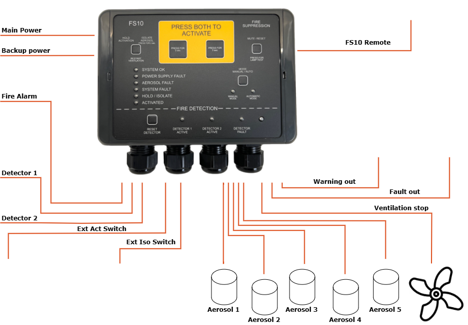
| No LEDs | No power | Check supply, technician |
| Power Supply Fault | 1 x flash | Check Main Power, technician |
| 2 x flash | Check Backup Power, technician | |
| Aerosol Fault | 1 x flash | Check Aerosol 1, technician |
| 2 x flash | Check Aerosol 2, technician | |
| 3 x flash | Check Aerosol 3, technician | |
| 4 x flash | Check Aerosol 4, technician | |
| 5 x flash | Check Aerosol 5, technician | |
| System Fault | 1 x flash | Check Ext. Act Switch, technician |
| 2 x flash | Check Ext. Iso. Switch, technician | |
| 3 x flash | Check Monitoring, technician | |
| 4 x flash | Internal fault, contact technician | |
| 5 x flash | Remote panel not connected, contact technician | |
| Detector Fault | 1 x flash | Check Detector 1, technician |
| 2 x flash | Check Detector 2, technician | |
| No LEDs on remote Panel | No power on Main Unit or disconnected or not configured correctly | Check Main Unit Check supply Check connection Check configuration Technician |
| Remote Panel, other faults | Misc. | Check Main Unit and troubleshooting for Main Unit |
 This Appendix provides operational guidance for the FS10 Remote Panel for the FS10 system.
## SYSTEM OVERVIEW
### System Purpose
The FS10 Remote Panel is a remote control and monitoring unit for the FS10 System.
### System description
The purpose of the FS10 Remote Panel is to have a slim, smooth and more elegant panel for bridges or a like. It is connected to the FS10 Main Unit, which can be mounted just outside the protected area.
Every relevant info for the FS10 system is shown, and action can be taken on the front of the FS10 Remote Panel.
### Main System Functions
- Connected to the FS10 Main Unit by a 4-wired cable, the FS10 Remote Panel are able to:
- Continuous system supervision.
- Fire alarm detection.
- Manual and automatic activation.
- Activation delay sequence.
- Warning outputs.
- Ventilation relay control.
- System fault indication.
- Dual power input monitoring.
- Event logging.
### System Components
- Connected to the FS10 Main Unit – and units connected to that.
## CONTROLS AND INDICATORS
### Remote Panel Overview, Front
This Appendix provides operational guidance for the FS10 Remote Panel for the FS10 system.
## SYSTEM OVERVIEW
### System Purpose
The FS10 Remote Panel is a remote control and monitoring unit for the FS10 System.
### System description
The purpose of the FS10 Remote Panel is to have a slim, smooth and more elegant panel for bridges or a like. It is connected to the FS10 Main Unit, which can be mounted just outside the protected area.
Every relevant info for the FS10 system is shown, and action can be taken on the front of the FS10 Remote Panel.
### Main System Functions
- Connected to the FS10 Main Unit by a 4-wired cable, the FS10 Remote Panel are able to:
- Continuous system supervision.
- Fire alarm detection.
- Manual and automatic activation.
- Activation delay sequence.
- Warning outputs.
- Ventilation relay control.
- System fault indication.
- Dual power input monitoring.
- Event logging.
### System Components
- Connected to the FS10 Main Unit – and units connected to that.
## CONTROLS AND INDICATORS
### Remote Panel Overview, Front
 ### Indicators and buttons
1. **Press Both to Activate**
> Press the two buttons in the middle at the same time for 3sec. to release the FS10 system. The pre-programmed delay time, before release, will start, and the internal buzzer will be beeping, and steady when released.
2. **Hold / Restart Button**
> This button has four functions.
- HOLD:
Press to hold the delay time when the FS10 is activated for release.
Press 20sec to cancel an activation.
- ISOLATE:
Press 3 sec. to activate isolation mode to the aerosol generator.
- RESTART:
Press to re-start the ventilation in the protected area, after the FS10 system has been released.
- To make a lamptest, press and hold button for \> 3 sec.
**\**
3. **Mode Button**
> Press MODE to change from manual to automatic release if it is set available during configuration.
4. **Mute / Reset Button**
- Press the MUTE / RESET button to mute the internal buzzer when a fault occurs.
- Press the MUTE / RESET button to reset fault indicator, when it is ok again.
- For lamp test press the MUTE / RESET button for 3sec.
5. **System OK indicator**
> When the FS10 system is powered up without any fault, the SYSTEM OK will be steady green.
6. **Hold / Isolate indicator**
> Will be steady orange when HOLD or ISOLATE mode is activated.
7. **Manual Mode and Automatic Mode Indicators**
> Will be green and show whether MANUAL or AUTOMAIC mode is chosen
>
> Press MODE to change from manual to automatic release if it is set available during configuration.
8. **Fault indicator**
> The fault indicator (red) turns on if any fault occurs on the FS10 system
>
> Press MODE to change from manual to automatic release if it is set available during configuration.
9. **Activated indicator**
> The ACTIVATED indicator (orange) will be flashing in the pre-programmed delay time before release. And steady when released.
10. **Fire Alarm indicator**
> The FIRE ALARM indicator will be on if the devices connected to the detector input are active on the FS10 system.
11. **Photo diode**
> Will dimmer the LEDs on the FS10 Remote panel when the dark is coming.
# Appendix C
## FS10 External Activation Switch
FS10 External Activation Switch makes it possible to activate the Aerosol Generators without having direct access to the FS10 panel. For example, it can be placed just outside the protected area where it must be possible to activate the Aerosol Generators.
### Indicators and buttons
1. **Press Both to Activate**
> Press the two buttons in the middle at the same time for 3sec. to release the FS10 system. The pre-programmed delay time, before release, will start, and the internal buzzer will be beeping, and steady when released.
2. **Hold / Restart Button**
> This button has four functions.
- HOLD:
Press to hold the delay time when the FS10 is activated for release.
Press 20sec to cancel an activation.
- ISOLATE:
Press 3 sec. to activate isolation mode to the aerosol generator.
- RESTART:
Press to re-start the ventilation in the protected area, after the FS10 system has been released.
- To make a lamptest, press and hold button for \> 3 sec.
**\**
3. **Mode Button**
> Press MODE to change from manual to automatic release if it is set available during configuration.
4. **Mute / Reset Button**
- Press the MUTE / RESET button to mute the internal buzzer when a fault occurs.
- Press the MUTE / RESET button to reset fault indicator, when it is ok again.
- For lamp test press the MUTE / RESET button for 3sec.
5. **System OK indicator**
> When the FS10 system is powered up without any fault, the SYSTEM OK will be steady green.
6. **Hold / Isolate indicator**
> Will be steady orange when HOLD or ISOLATE mode is activated.
7. **Manual Mode and Automatic Mode Indicators**
> Will be green and show whether MANUAL or AUTOMAIC mode is chosen
>
> Press MODE to change from manual to automatic release if it is set available during configuration.
8. **Fault indicator**
> The fault indicator (red) turns on if any fault occurs on the FS10 system
>
> Press MODE to change from manual to automatic release if it is set available during configuration.
9. **Activated indicator**
> The ACTIVATED indicator (orange) will be flashing in the pre-programmed delay time before release. And steady when released.
10. **Fire Alarm indicator**
> The FIRE ALARM indicator will be on if the devices connected to the detector input are active on the FS10 system.
11. **Photo diode**
> Will dimmer the LEDs on the FS10 Remote panel when the dark is coming.
# Appendix C
## FS10 External Activation Switch
FS10 External Activation Switch makes it possible to activate the Aerosol Generators without having direct access to the FS10 panel. For example, it can be placed just outside the protected area where it must be possible to activate the Aerosol Generators.
 1. **Open Lid and press the button\**
Open lid and press the button to Activate the Aerosol Generators.
The pre-programmed delay time, before release, will start
At the FS10 Main Unit the LED for Activation will be lid and the internal buzzer will be beeping, and steady when released.
# Appendix D
## FS10 External Isolation Switch
FS10 External Isolation Switch makes it possible to activate “ISOLATE” or “HOLD” mode without having direct access to the FS10.
Due to safety distance from the Aerosol Generators, we recommend to place an External Isolation Switch just outside the protected area, making it possible to Isolate the Aerosol Generators before entering the protected area – and to “de-isolate” when leaving again.
The ON LED will be green when system is ON, and the ISO LED will be yellow when the system is isolated
1. **Open Lid and press the button\**
Open lid and press the button to Activate the Aerosol Generators.
The pre-programmed delay time, before release, will start
At the FS10 Main Unit the LED for Activation will be lid and the internal buzzer will be beeping, and steady when released.
# Appendix D
## FS10 External Isolation Switch
FS10 External Isolation Switch makes it possible to activate “ISOLATE” or “HOLD” mode without having direct access to the FS10.
Due to safety distance from the Aerosol Generators, we recommend to place an External Isolation Switch just outside the protected area, making it possible to Isolate the Aerosol Generators before entering the protected area – and to “de-isolate” when leaving again.
The ON LED will be green when system is ON, and the ISO LED will be yellow when the system is isolated
 1. **Hold / Isolate Button**
> This button has three functions.
- HOLD:
Press to hold the delay time when the FS10 is activated for release
Press 20sec to cancel an activation
- ISOLATE:
Press 3sec to activate isolate mode to the aerosol generator
- RESTART:
Press to re-start the ventilation in the protected area, after the FS10 system has been released
> At the FS10 Main Unit the LED for Hold´/ Isolate will be lid.
# Appendix E
## FS10 Connection Box
1. **Hold / Isolate Button**
> This button has three functions.
- HOLD:
Press to hold the delay time when the FS10 is activated for release
Press 20sec to cancel an activation
- ISOLATE:
Press 3sec to activate isolate mode to the aerosol generator
- RESTART:
Press to re-start the ventilation in the protected area, after the FS10 system has been released
> At the FS10 Main Unit the LED for Hold´/ Isolate will be lid.
# Appendix E
## FS10 Connection Box
 FS10 Connection Box makes sense when you have multiple Aerosol Generators attached to the FS10.
In this way you can save on the use of cable, and it makes the mounting in the FS10 easier.
FS10 Connection Box makes sense when you have multiple Aerosol Generators attached to the FS10.
In this way you can save on the use of cable, and it makes the mounting in the FS10 easier.
