FS10 User Manual
User Manual for the FS10 Control and Monitoring System for Fixed Aerosol Fire Extinguishing Installations
- Introduction
- Safety Information
- System Overview
- Controls and Indicators
- Normal Operation
- Fire Alarm Operation
- Abnormal & Emergency Conditions
- Operator Maintenance
- Troubleshooting
- Document References
- Appendix
Introduction
Purpose of the Manual
This manual provides operational guidance for the FS10 system. It describes normal operation, fire response, manual and automatic activation, fault indications, and operator-level maintenance procedures. Installation, service, cabling, and configuration are covered in the FS10 Service Manual.
Scope
This document covers:
-
Day-to-day operation.
-
System status indications.
-
Fire alarm handling.
-
Manual and automatic activation logic.
-
Fault interpretation.
-
Basic operator maintenance.
-
Operational limitations and safety information.
It does not cover:
-
Electrical installation.
-
Firmware configuration.
-
Commissioning and testing.
-
Internal servicing. (see FS10 Service Manual).
Intended Audience
This manual is intended for:
-
Vessel crew.
-
Bridge operators.
-
Personnel responsible for fire safety equipment.
It is not intended for technicians, installers, or service engineers.
Related Documentation
-
FS10 Service Manual.
-
FS10 Datasheet.
-
FS10 Firmware Update Guide.
-
Aerosol Generator Manufacturer Data.
-
ISO 9094:2022.
-
ISO 10240:2019.
System Compliance and Intended Use
The FS10 system is compliant with DS/ISO 9094:2022 and intended for use in non-IMO marine applications, including:
-
Engine rooms.
-
Technical compartments.
-
Machinery spaces.
-
Enclosed utility spaces.
Symbol and Icon Note
The FS10 uses standardized colors and symbols for indicators and operational states. LED indicator meanings are defined in 4.3 Indicator table.
Additional technical symbols, detailed wiring symbols, and service-level icons are defined in the FS10 Service Manual.
Onboard Use and Accessibility Note
This User Manual shall be kept readily accessible to crew members responsible for fire safety.
It is recommended that the manual is stored near the FS10 Main Unit or at an appropriate location on the bridge or in the technical documentation binder for the vessel.
The manual is intended for operational use only; installation and service must follow the FS10 Service Manual.
Safety Information
Safety Definitions

WARNING – Hazard that may cause serious injury or death.
CAUTION – Risk of equipment damage.
NOTICE – Operationally important information.
General Safety Warnings
WARNING – Automatic Fire Suppression The system may activate automatically. Do not enter the protected area during a fire event.
WARNING – Manual Activation Hazard Once the activation pulse is sent, leave the protected area. Discharge can be cancelled, see 4.2 Indicators and buttons.
WARNING – Visibility and Atmosphere Aerosol discharge reduces visibility and there is a safety distance to the Aerosol generators, please follow subscriptions for Aerosol Generators.
WARNING – Ventilation Shutdown Ventilation stops automatically during activation. Ventilation can be restarted after activation.
Equipment Handling Warnings
CAUTION – Electrical Hazard Do not open the FS10 enclosure during operation.
CAUTION – Aerosol Circuit Handling Only trained personnel may connect or disconnect aerosol generators.
NOTICE – External Switches Ensure that external activation, hold or isolation switches remain accessible.
Operational Limitations
-
Supports up to 5 aerosol generators.
-
Intended for non-IMO vessels.
-
Operator actions are limited to this manual.
Entry After Discharge
-
Ensure discharge is complete.
-
Ventilation must be restarted, when fire is extinguished.
-
Only enter when visibility is sufficient.
Automatic Mode Safety
If FS10 is configured to Automatic Mode, BEWARE: automatic activation may occur without operator input.
System Overview
System Purpose
The FS10 is a dedicated control and monitoring system for fixed aerosol fire suppression systems in non-IMO marine applications.
You find the FS10 system in two variants, a normal bracket mount unit and a flush mount unit, the function is the same in both variants.
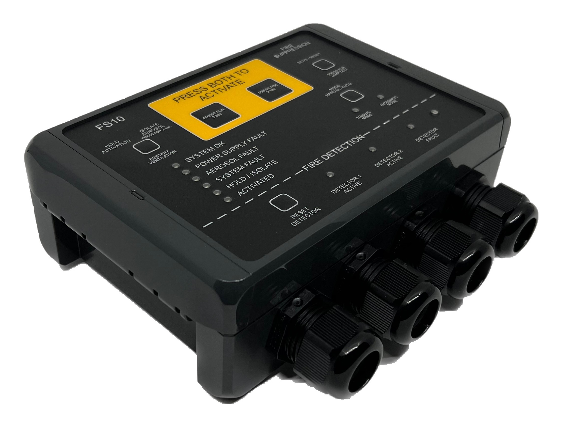
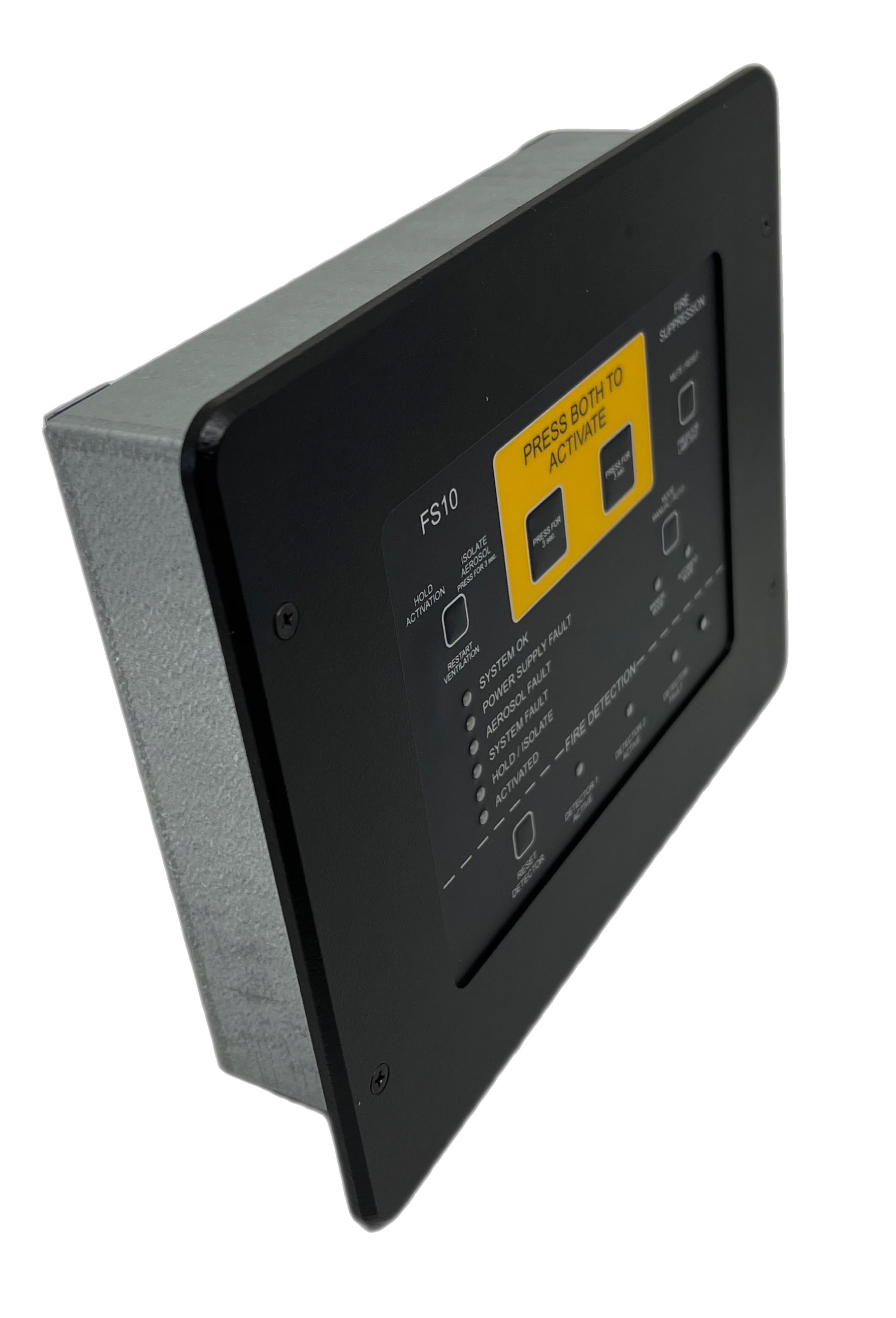
FS10 main for bracket mount FS10 main - Flush Mount
System description
The purpose of the FS10 system is to control and monitor a number of aerosol generators mounted in the area to be secured part of a fire extinguishing system.
The primary purpose of the FS10 system is to activate the aerosol generators in event of fire.
The secondary purpose of the FS10 system is to monitor the system itself (e.g. power supplies, aerosol connections, cables and individual system components) and give an alarm if a fault within the system is detected.
Furthermore, two inputs are provided for smoke detectors. The system can be configured (during commissioning) to automatically activate the aerosol generators if one or both detector inputs are active.
Main System Functions
-
Continuous system supervision.
-
Dual power input monitoring.
-
Manual and / or automatic activation.
-
Activation delay sequence.
-
Warning outputs.
-
Ventilation relay control.
-
System fault indication.
-
Fire alarm detection.
-
Event logging.
System Components
-
FS10 Main Unit.
-
Aerosol generators (generic).
-
Remote Panel (optional).
-
External activation switch (optional).
-
External hold/isolation switch (optional).
-
Warning devices.
-
Detectors 2 zones (optional).
System Architecture
System Architecture Overview:
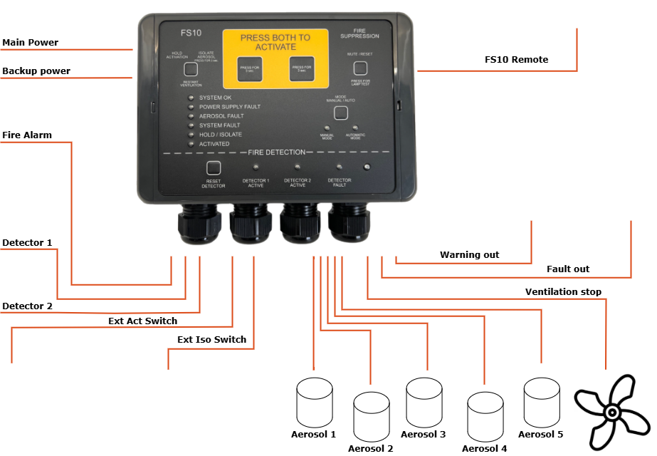
System Behaviour Summary
| Condition | Behaviour |
|---|---|
| Power ON | Self-test, System OK (green) |
| Fault | Fault LED (yellow), Fault relay NO, buzzer |
| Fire | Fire LED (red), fire alarm out, buzzer |
| Activation | Activation LED blinking (solid after discharge), warning out, buzzer |
Accessories
-
Remote Panel (see Appendix B).
-
External Activation Switch (see Appendix C).
-
External Hold/Isolation Switch (see Appendix D).
Controls and Indicators
Front Panel Overview

Indicators and buttons
For manual activation in case of fire hold both buttons for at least 3 seconds to activate the aerosol generators. The aerosol generators will be activated after an activation delay set during commissioning (typically 20 seconds).
2. Hold / Isolate / Restart Ventilation button
The hold/isolate input serves more functions:
Hold functionality, which temporarily delays the activation of the aerosols after the activation procedure has started.
Cancel functionality, pressing the button for at least 20 seconds will cancel the activation.
Isolate functionality, which permanently disables the activation of aerosols while work is being carried out in the protected area.
Restart Ventilation functionality; During activation, any ventilation systems or similar connected to the FS10 ventilation output will be shut down. After extinction of the fire, the ventilation may be turned on again by pressing the button.
3. OK indicator
The OK indicator (green) is lit under normal operation. Note that under all circumstances at least one indicator on the FS10 front panel must be lit. Please consult the FS10 Service Manual for further details.
4. Fault indicators
If a fault condition is detected by the FS10 system, the corresponding fault indicator (yellow) will be lit.
5. Hold indicator
The hold indicator is lit when hold function is active (i.e., when the Hold button (2) is pressed).
6. Activate indicator
The Activate indicator (orange) will be blinking during the activation delay period and will be permanently lit when aerosols have been activated.
7. Detector reset button
8. Detector indicators
The relevant detector indicator(s) will be permanently lit if a connected Manual Call Point is in alarm state or blinking if a connected automatic detector is in alarm state.
9. Mode indicators
Indicators showing whether the FS10 panel is in automatic or manual mode. In manual mode activation can only happen by pressing the Activation buttons (1) or by using an external activation switch. In automatic mode activation can be started by 1 or 2 active detector inputs or manually as in manual mode.
10. Mode selector button
If configured; switch between automatic and manual mode, hold the button for at least 3 seconds.
11. Mute / reset / lamptest button
Faults: If a fault is detected, the corresponding indicator is lit, and the internal buzzer and the fault condition is signalled to any external device connected by pressing the button, the internal buzzer is muted.
When the fault condition has been remedied, the fault indicator and the external fault output may also be reset by pressing the button.
Fire:
If fire is detected, the corresponding indicator is lit, and the internal buzzer and the fire condition is signalled to any external device connected, by pressing the button, the internal buzzer is muted.
Lamptest: To make a lamptest, press and hold button for > 3 sec.
Fault conditons: If a fault occurs, press button for > 3 sec. and LED will show fault pattern, see 7.2 Common Faults.
12. Internal buzzer
The internal buzzer is turned on when a fault condition is detected or when a detector input goes to alarm state. It will also be bleeping when activation of aerosol generators has been started.
Indicator table
| Name | LED | Meaning |
|---|---|---|
| System OK | Green | System operational |
| Faults | Yellow | Fault present |
| Fire Alarm | Red | Fire detected |
| Activation | Orange (blink) | Delay running |
| Activation | Orange (solid) | Aerosol discharge complete |
| Detector Zone | Red | Detector active |
Interaction Table
| Action | Response |
|---|---|
| Press both activation buttons | Delay begins |
| Press Hold/Cancel | Delay stops / cancel |
| Press Isolate > 3 sec. | Isolate Aerosol Generators |
| Detector activation | Fire alarm |
| Fault detected | Fault alert |
| Restart ventilation, ONLY after release | Ventilation ON |
Normal Operation
Power-On Behaviour
-
System OK LED must turn green.
-
Fault LED must be off.
-
No audible fault indications.
Monitoring Mode
The FS10 continuously monitoring aerosols, power, switches, and internal circuits.
FS10 also monitoring external detectors, fire alarms and warning devices, if configured so.
Daily Check (Recommended)
-
Verify System OK (green).
-
No faults active.
-
No fire alarms active.
-
External switches in correct positions.
Manual vs Automatic Mode
Manual Mode
Activation must be triggered by operator or external activation switch.
Automatic Mode
Activation may occur when 1 and 2, or 1 or 2 detector zones trigger (depending on configuration).
Buzzer Patterns
| Pattern | Meaning |
|---|---|
| Constant beeps | Fault |
| Repeated beeps | Activation delay |
| Constant beeps | Activation completed |
Prohibited Operator Actions
-
Do not open enclosure.
-
Do not rewire.
-
Do not disconnect aerosols.
-
Do not change internal configuration.
Fire Alarm Operation
Fire Detection
-
Fire LED (red).
-
Buzzer active.
-
Fire relay active.
Automatic Activation Sequence (if enabled)
-
Fire detected.
-
Activation delay begins.
-
Activation LED blinks.
-
Warning devices activate.
-
Aerosol discharge occurs after delay.
Manual Activation Procedure
-
Press and hold both activation buttons simultaneously for ≥ 3 seconds.
-
Activation delay begins.
-
Activation LED blinks.
-
Warning devices activate.
-
Aerosol discharge occurs after delay.
Hold/Cancel
-
Delay time can be hold if button is pressed.
-
Cancel activation by pressing button ≥ 20 seconds.
Ventilation Shutdown and Restart
-
Ventilation OFF during activation.
-
Restart ventilation manually when safe.
After a Fire Event
-
Restart ventilation.
-
Confirm fire extinguished.
-
Technician inspection required.
Sticker, user quick guide
-
The sticker, enclosed to the FS10 Main Unit, gives a quick introduction to the user of the FS10 Main Unit.
-
It is recommended to setup the sticker next to the FS10 Main Unit, making all able to use the FS10 Main Unit in an emergency situation.
-
Sticker:

Abnormal & Emergency Conditions
General Fault Behaviour
- Fault LED (yellow).
- Buzzer intermittent.
- Fault relay active.
Common Faults
- See 9, TROUBLESHOOTING
Operator Maintenance
Permitted Tasks
-
Visual inspection.
-
Indicator check.
-
Alarm acknowledgement.
Prohibited Tasks
-
Opening enclosure.
-
Wiring changes.
-
Firmware changes.
-
Aerosol connection.
Routine Inspection
-
Make sure at least one LED is lid.
-
Check for No Fault on system.
Troubleshooting
Detecting faults
| Flashing LED | Numbers of Flash . | Action |
|---|---|---|
| No LEDs | No power | Check supply, technician |
| Power Supply Fault | 1 x flash | Check Main Power, technician |
| 2 x flash | Check Backup Power, technician | |
| Aerosol Fault | 1 x flash | Check Aerosol 1, technician |
| 2 x flash | Check Aerosol 2, technician | |
| 3 x flash | Check Aerosol 3, technician | |
| 4 x flash | Check Aerosol 4, technician | |
| 5 x flash | Check Aerosol 5, technician | |
| System Fault | 1 x flash | Check Ext. Act Switch, technician |
| 2 x flash | Check Ext. Iso. Switch, technician | |
| 3 x flash | Check Monitoring, technician | |
| 4 x flash | Internal fault, contact technician | |
| 5 x flash | Remote panel not connected, contact technician | |
| Detector Fault | 1 x flash | Check Detector 1, technician |
| 2 x flash | Check Detector 2, technician | |
| No LEDs on remote Panel | No power on Main Unit or disconnected or not configured correctly | Check Main Unit Check supply Check connection Check configuration Technician |
| Remote Panel, other faults | Misc. | Check Main Unit and troubleshooting for Main Unit |
Technician Required
-
Persistent faults.
-
Internal error.
-
Any activation event.
-
Change of configuration.
Document References
The FS10 system is supported by the following documents:
| Document | Description |
|---|---|
| FS10 Service Manual | Installation, wiring, commissioning, diagnostics, fault scenarios. |
| FS10 Datasheet | Technical specifications for power, detectors, aerosols, relays. |
| FS10 Firmware Update Guide | How to update firmware via BLE dongle and PC browser. |
| FS10 Installation Drawings | Mounting, spacing, cable routing (provided separately). |
| Aerosol Generator Documentation | Manufacturer data for individual aerosol devices (generic reference). |
| ISO 9094:2022 | Standard for fire protection of small craft. |
| ISO 10240:2019 | Standard for structure and content of shipborne user manuals (basis for this document). |
Appendix
Appendix A
FS10 Main Unit, Activating the aerosol generators
-
Press both Activation buttons (1) for at least 3 seconds.
-
The ventilation in the protected area is turned off.
-
The activation delay time elapses. (0s-120s, set during commissioning). During this time the external release warning device is turned on, the internal buzzer is bleeping and the Activate indicator (6) is blinking. It is possible to hold the activation by pressing or holding the Hold button (2). Activation will be hold while the button is pressed down. Activation delay “countdown” continues when releasing the button. Activation will be aborted if the Hold Button is pressed for more than 20 seconds.
-
The aerosol generators are activated.
-
After activation the internal buzzer and the Activate indicator (6) are turned on permanently. The internal buzzer may be turned off by pressing the Mute / Reset button (11).
-
After complete extinction of fire, the ventilation in the protected area may be restarted by pressing the Restart Ventilation button (2).
Fire alarm handling – Manual mode
-
If the required detector inputs are in alarm state (set during commissioning), the internal buzzer and external fire alarm device is turned on.
-
The internal buzzer and external fire alarm device may be turned off by pressing the Mute / Reset button (11).
-
If deemed necessary, the aerosol generators may be activated to extinguish the fire. Do this by pressing both the Activation buttons (1) for > 3 seconds as described above.
-
When the fire or smoke is no longer present, the fire alarm may be reset by pressing the pressing the Mute / Reset Detector button (11).
Fire alarm handling – Automatic mode
- If the required detector inputs are in alarm state (set during commissioning), the internal buzzer and external fire alarm device is turned on, and delay time is activated before the aerosol generators is released. See section 4 for instructions on activation. See section 5 for instructions on fire alarm handling.
Appendix B
FS10 Remote Panel
 This Appendix provides operational guidance for the FS10 Remote Panel for the FS10 system.
SYSTEM OVERVIEW
System Purpose
The FS10 Remote Panel is a remote control and monitoring unit for the FS10 System.
System description
The purpose of the FS10 Remote Panel is to have a slim, smooth and more elegant panel for bridges or a like. It is connected to the FS10 Main Unit, which can be mounted just outside the protected area.
Every relevant info for the FS10 system is shown, and action can be taken on the front of the FS10 Remote Panel.
Main System Functions
-
Connected to the FS10 Main Unit by a 4-wired cable, the FS10 Remote Panel are able to:
-
Continuous system supervision.
-
Fire alarm detection.
-
Manual and automatic activation.
-
Activation delay sequence.
-
Warning outputs.
-
Ventilation relay control.
-
System fault indication.
-
Dual power input monitoring.
-
Event logging.
-
System Components
- Connected to the FS10 Main Unit – and units connected to that.
CONTROLS AND INDICATORS
Remote Panel Overview, Front

Indicators and buttons
- Press Both to Activate
Press the two buttons in the middle at the same time for 3sec. to release the FS10 system. The pre-programmed delay time, before release, will start, and the internal buzzer will be beeping, and steady when released.
- Hold / Restart Button
This button has four functions.
-
HOLD: Press to hold the delay time when the FS10 is activated for release. Press 20sec to cancel an activation.
-
ISOLATE: Press 3 sec. to activate isolation mode to the aerosol generator.
-
RESTART: Press to re-start the ventilation in the protected area, after the FS10 system has been released.
-
To make a lamptest, press and hold button for > 3 sec.
**
Press MODE to change from manual to automatic release if it is set available during configuration.
-
Press the MUTE / RESET button to mute the internal buzzer when a fault occurs.
-
Press the MUTE / RESET button to reset fault indicator, when it is ok again.
-
For lamp test press the MUTE / RESET button for 3sec.
- System OK indicator
When the FS10 system is powered up without any fault, the SYSTEM OK will be steady green.
- Hold / Isolate indicator
Will be steady orange when HOLD or ISOLATE mode is activated.
- Manual Mode and Automatic Mode Indicators
Will be green and show whether MANUAL or AUTOMAIC mode is chosen
Press MODE to change from manual to automatic release if it is set available during configuration.
- Fault indicator
The fault indicator (red) turns on if any fault occurs on the FS10 system
Press MODE to change from manual to automatic release if it is set available during configuration.
- Activated indicator
The ACTIVATED indicator (orange) will be flashing in the pre-programmed delay time before release. And steady when released.
- Fire Alarm indicator
The FIRE ALARM indicator will be on if the devices connected to the detector input are active on the FS10 system.
- Photo diode
Will dimmer the LEDs on the FS10 Remote panel when the dark is coming.
Appendix C
FS10 External Activation Switch
FS10 External Activation Switch makes it possible to activate the Aerosol Generators without having direct access to the FS10 panel. For example, it can be placed just outside the protected area where it must be possible to activate the Aerosol Generators.

- *Open Lid and press the button* Open lid and press the button to Activate the Aerosol Generators. The pre-programmed delay time, before release, will start At the FS10 Main Unit the LED for Activation will be lid and the internal buzzer will be beeping, and steady when released.
Appendix D
FS10 External Isolation Switch
FS10 External Isolation Switch makes it possible to activate “ISOLATE” or “HOLD” mode without having direct access to the FS10.
Due to safety distance from the Aerosol Generators, we recommend to place an External Isolation Switch just outside the protected area, making it possible to Isolate the Aerosol Generators before entering the protected area – and to “de-isolate” when leaving again.
The ON LED will be green when system is ON, and the ISO LED will be yellow when the system is isolated

- Hold / Isolate Button
This button has three functions.
-
HOLD: Press to hold the delay time when the FS10 is activated for release Press 20sec to cancel an activation
-
ISOLATE: Press 3sec to activate isolate mode to the aerosol generator
-
RESTART: Press to re-start the ventilation in the protected area, after the FS10 system has been released
At the FS10 Main Unit the LED for Hold´/ Isolate will be lid.
Appendix E
FS10 Connection Box
 FS10 Connection Box makes sense when you have multiple Aerosol Generators attached to the FS10.
In this way you can save on the use of cable, and it makes the mounting in the FS10 easier.
